Electronics
The Ender-CNC electronics are intentionally simple. The control system is based on a standard Arduino Uno with a CNC Shield V3, driving TMC2209 stepper drivers.
Power is supplied by the original Ender 3 power supply, making the system compact and cost-efficient while maintaining reliability.
Core Components
The following elements make up the electrical system:
- Arduino Uno R3 — runs the GRBL firmware and manages motion control
- CNC Shield V3 — plugs directly into the Arduino and routes step/dir/enable signals
- TMC2209 Drivers (×3) — quiet, precise control for each motor (X, Y, Z)
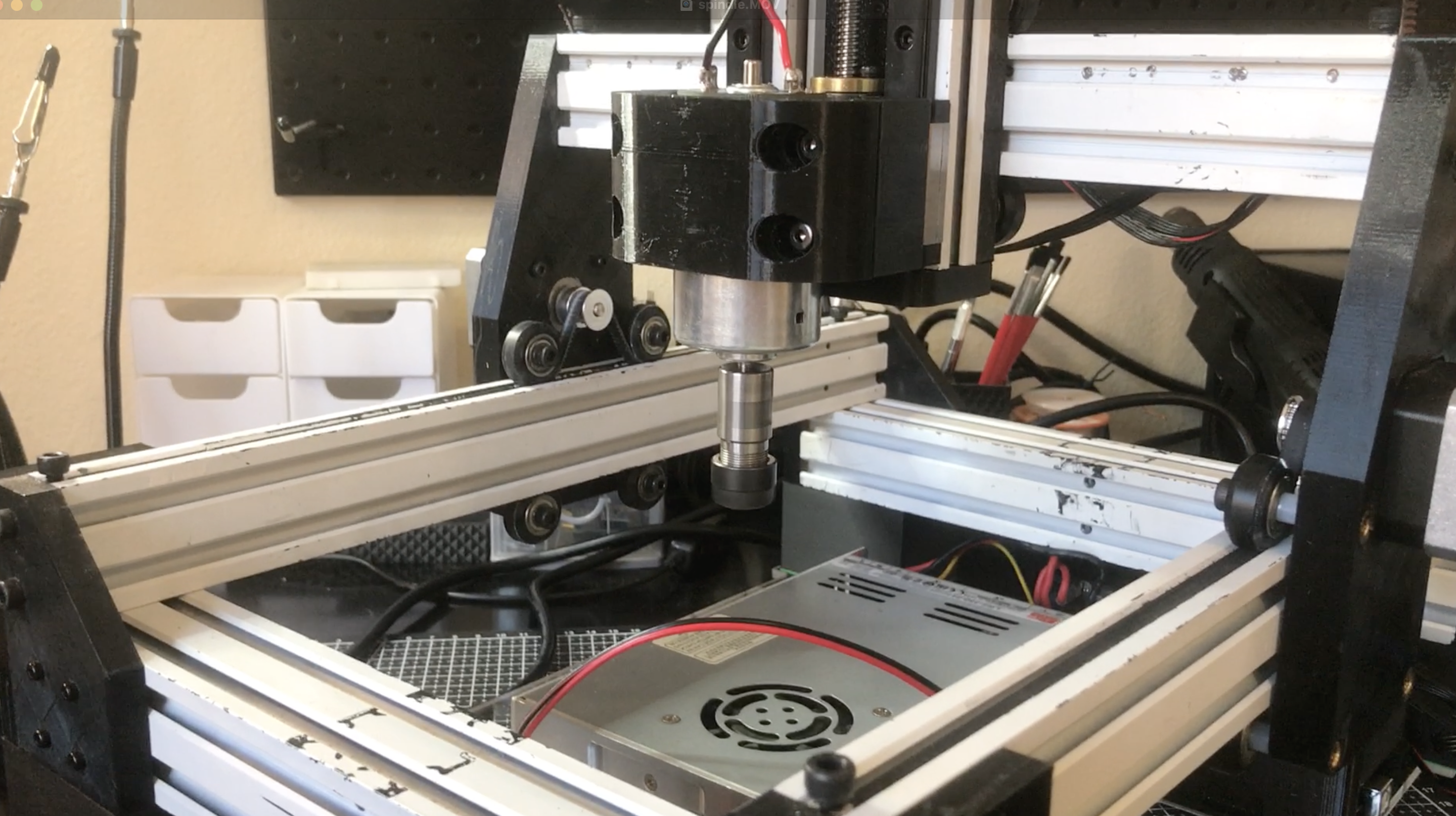
- 52 mm Spindle Motor — standard air-cooled motor, PWM-controlled via spindle driver board
- Ender 3 Power Supply (24 V) — reused from the printer; powers both logic and spindle controller
- Main Power Switch — reused for safety and convenience
Wiring Overview
Connections between components are straightforward:
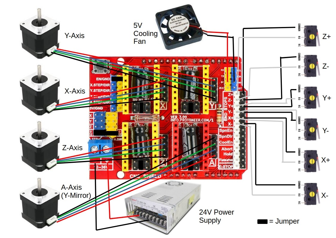
- The CNC Shield accepts X/Y/Z stepper motor connectors directly.
- The Spindle driver board connects to the CNC Shield’s spindle PWM output for speed control.
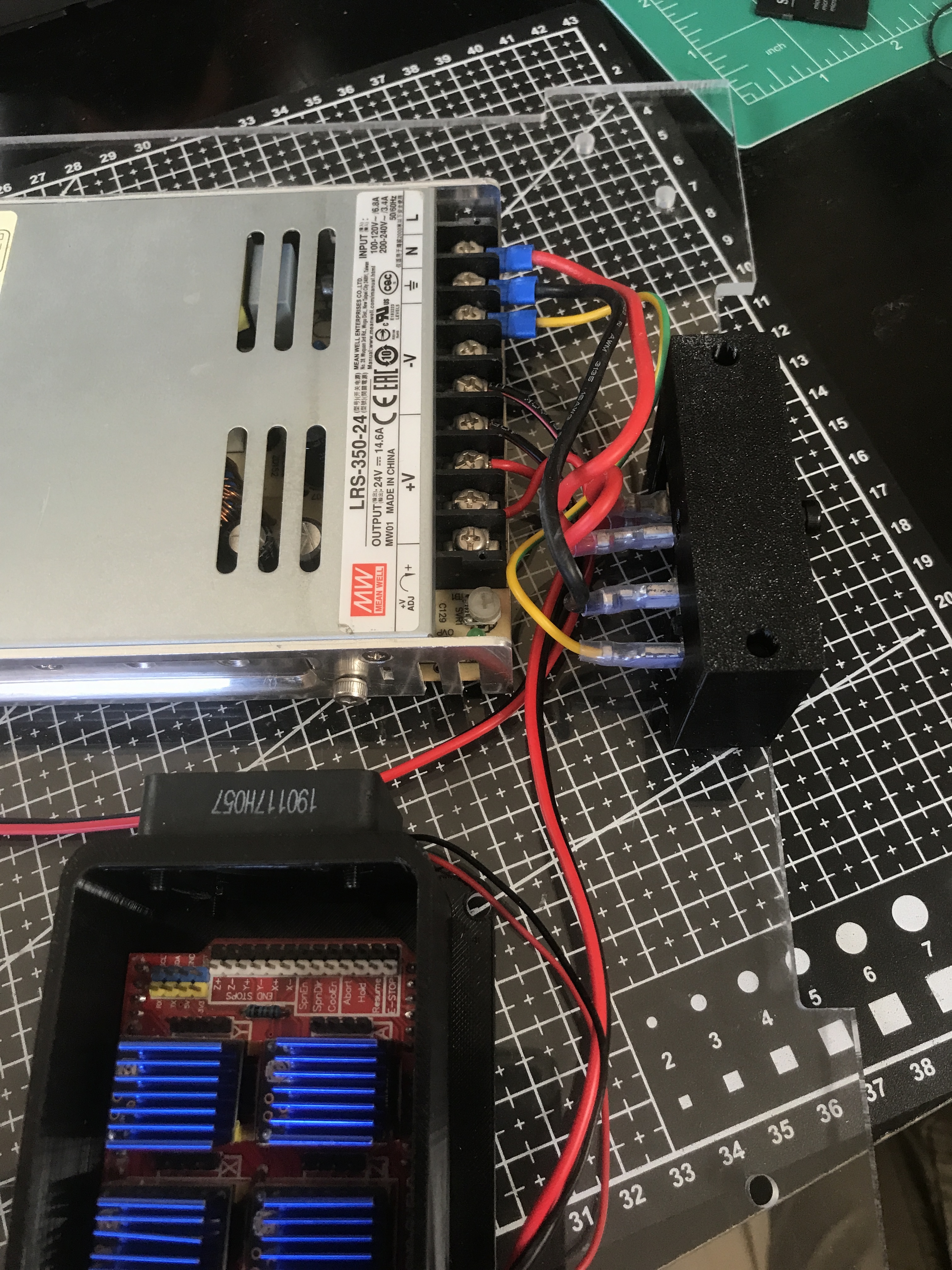
- 24 V input from the power supply feeds both the shield (via VIN) and the spindle controller.
- Ground all components to the same common reference point.
Double-check polarity before applying power — especially for the spindle driver module.
Incorrect wiring may permanently damage the Arduino or shield.
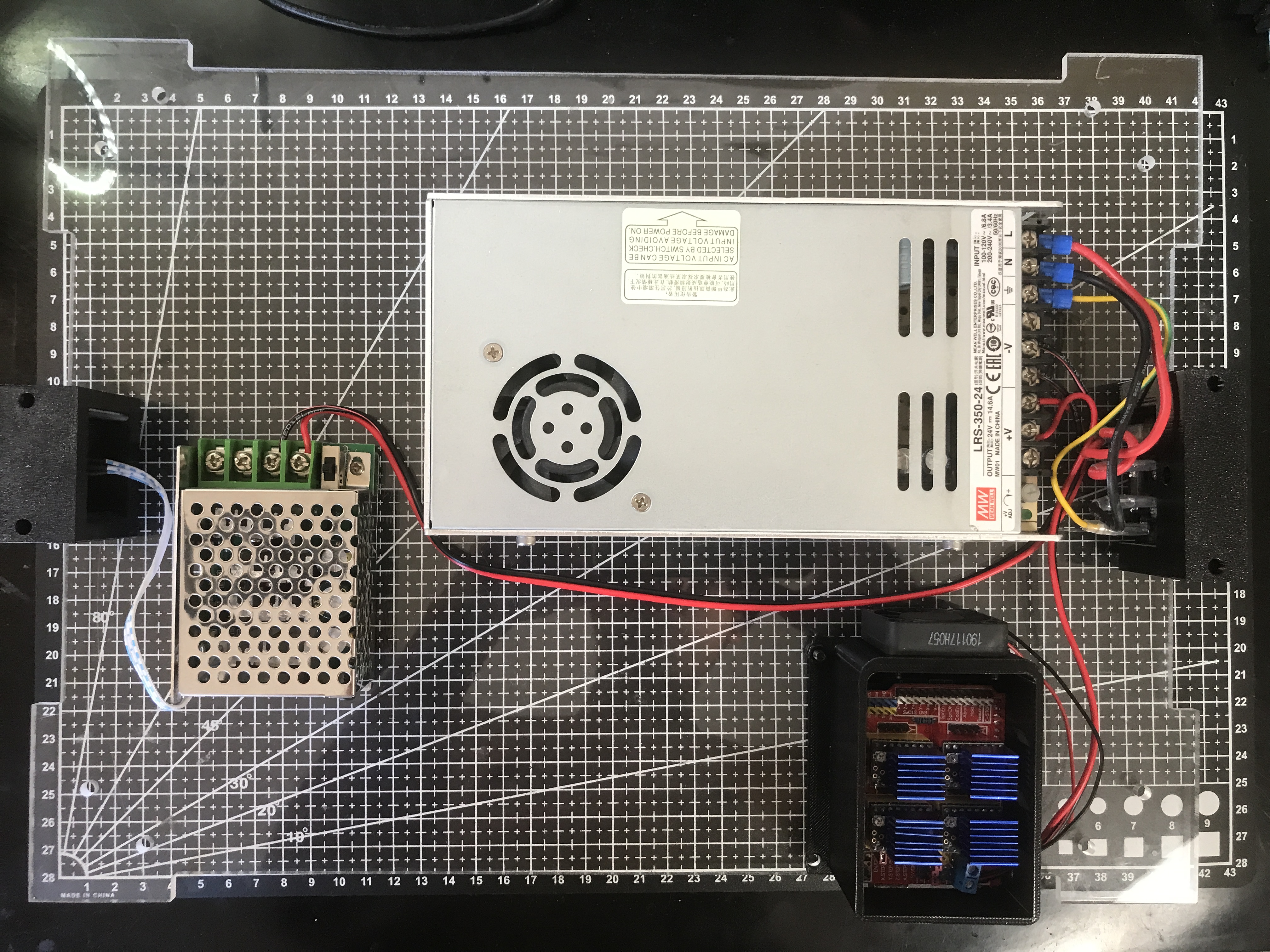
The Ender 3 power supply (24 V 15 A) provides all DC power for the system. AC mains input connects directly to the supply, and the original power switch can be reused. The DC output should feed both the CNC shield and the spindle, with the spindle always powered through its controller for proper speed regulation.
On the CNC shield, the screw terminals at the edge accept the main 24 V input. Connect the stepper motors according to the wiring diagram: the two parallel horizontal axes correspond to Y, the upper crossbar is X, and the vertical column is Z. Reusing the existing Ender 3 motor cables is recommended for consistency and reliability.
Ensure that the spindle controller and the CNC shield share a common ground. This prevents erratic PWM response and reduces electrical noise. Keep wiring as short as possible and route it away from moving parts to maintain signal integrity and mechanical safety.
TMC2209 Configuration
The TMC2209 drivers require two basic adjustments: motor current limit and microstepping. On a standard CNC Shield V3 (GRBL step/dir), set the current with the Vref trimpot on each driver, and set microstepping using the jumpers under each driver socket.
Refer to the driver tuning guide for the practical steps:
Set the current to match your stepper’s rated current—start conservatively, then raise only if you see missed steps. Use a consistent microstepping mode (commonly 1/8 or 1/16). Higher current will also lead to more heat produced.
Spindle Control
A standard 52 mm DC spindle is recommended for this build. Most low-cost units available on Amazon are suitable, provided they operate at 24 V and include their own PWM speed controller. The controller regulates spindle speed and typically accepts both a manual potentiometer input and an external PWM signal.
For basic operation, connect the spindle and controller directly to the 24 V power supply and use the potentiometer for manual speed adjustment. If preferred, the controller’s PWM input can also be connected to the CNC Shield’s spindle output pin (D11) for software-based speed control through GRBL.
If automated control is desired, GRBL supports PWM-based spindle commands — use M3 S### to set speed and M5 to stop.
Summary
- Reuse the Ender 3 power supply and main switch.
- Use Arduino Uno + CNC Shield V3 + TMC2209 for motion control.
- Integrate a 52 mm PWM-controlled spindle.
- Keep wiring neat, grounded, and secured.