Z-Axis & Drive Integration
The Z-Rails & Motion stage finalizes the mechanical assembly of the Ender-CNC.
In this step, you’ll install the linear rails, coupler, lead screw, bearings, and spindle holder — completing the full 3-axis motion system.
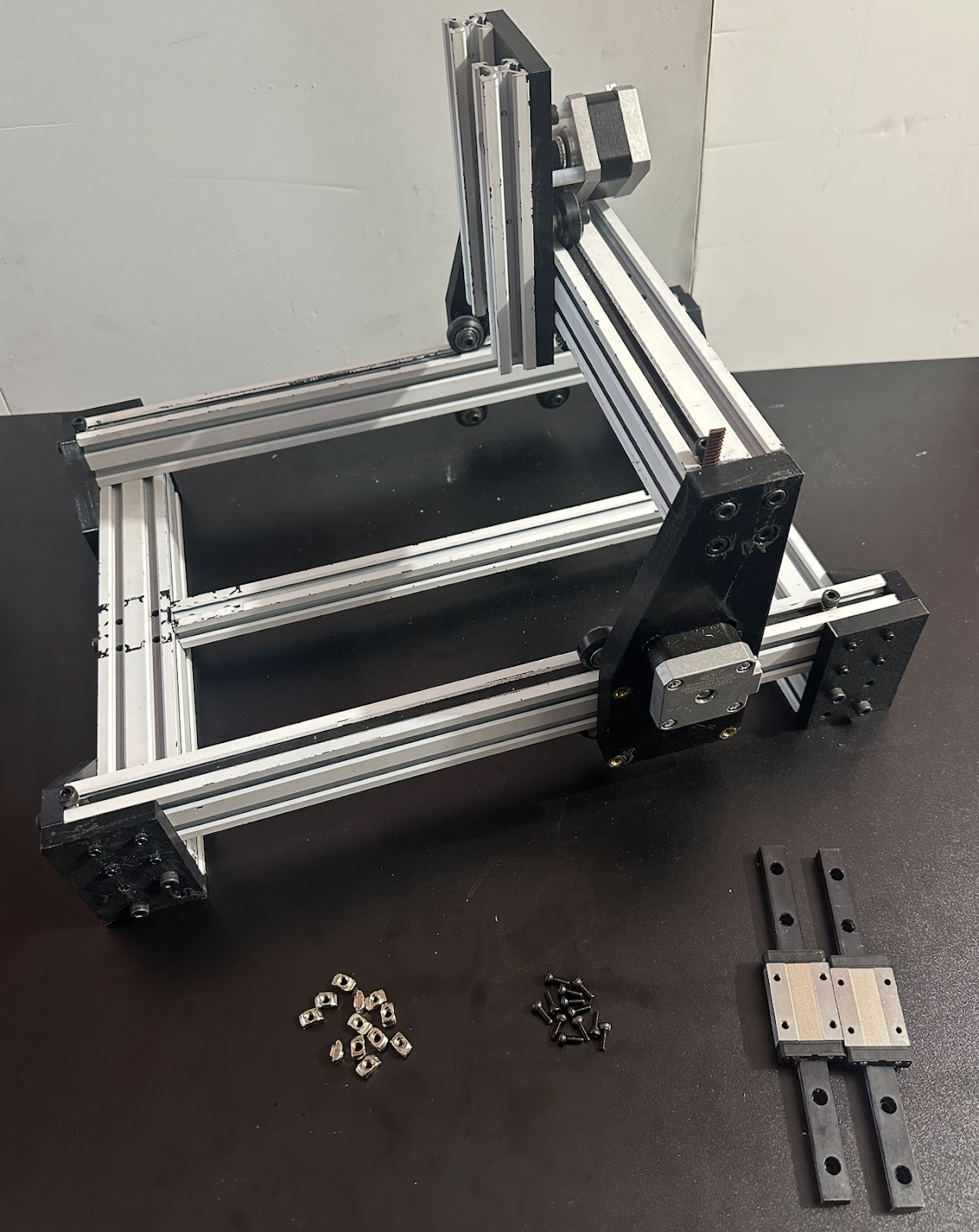
Linear Rail Installation
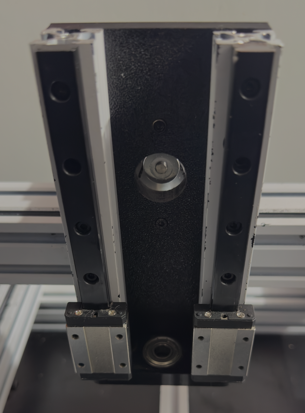
Begin by installing the MGN12 linear rails onto the vertical extrusions.
Alignment is critical — both rails must remain perfectly parallel along their full length.
Misaligned rails will cause carriage binding and inconsistent Z-axis motion.
Use calipers or spacers to ensure equal spacing top and bottom.
Coupler and Motor Connection
Attach the shaft coupler to the NEMA 17 Z-axis motor.
While a pancake motor can be used, a standard NEMA 17 offers better torque and stability.
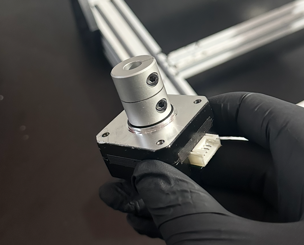
Ensure the coupler is centered and fully seated on the shaft.
Tighten both set screws evenly to prevent wobble.
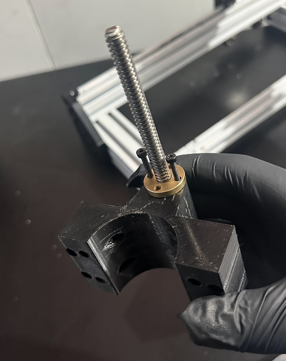
Lead Screw & Nut Assembly
Insert the lead screw (cut from your Ender 3) into the spindle mount.
Secure it using M3 bolts and a brass lead-screw nut.
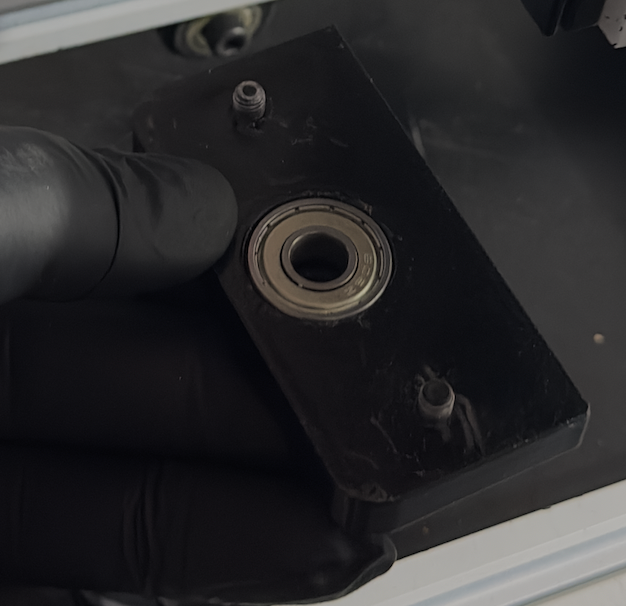
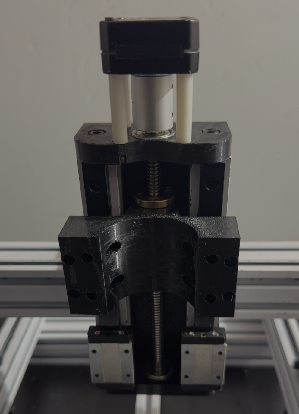
Bearing and Top Mount Integration
Insert the bearing into the top bracket, then fasten it with M3 bolts and spacers to prepare for motor mounting.
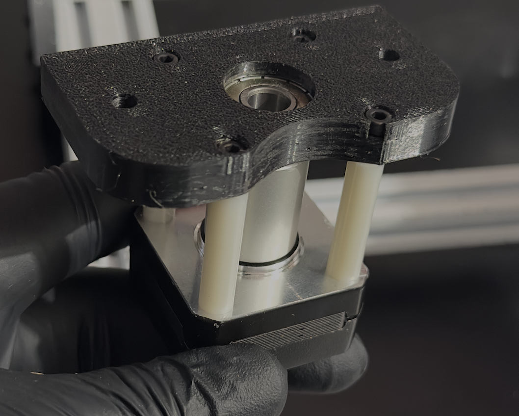
Join both upper and lower components together, ensuring they align concentrically with the lead screw.
Install the lower bracket assembly by inserting M5 bolts into its base, then tightening the bearing housing firmly in place.
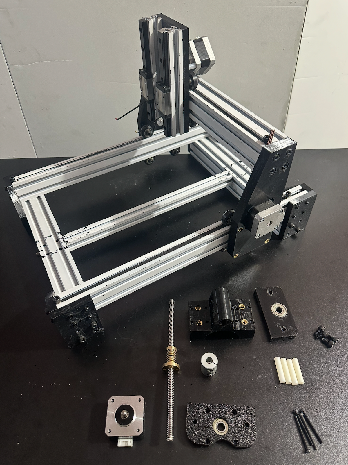
Assembling onto the Frame
At this stage, your full subassembly should resemble the photo below.
Carefully mount the lead-screw motor unit onto the machine frame.
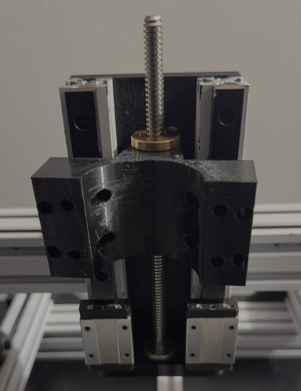
Next, attach the top motor support and tighten securely to constrain all vertical motion.
Fasten M3 bolts through the motor mount holes into the MGN12 carriage to secure the spindle drive assembly.
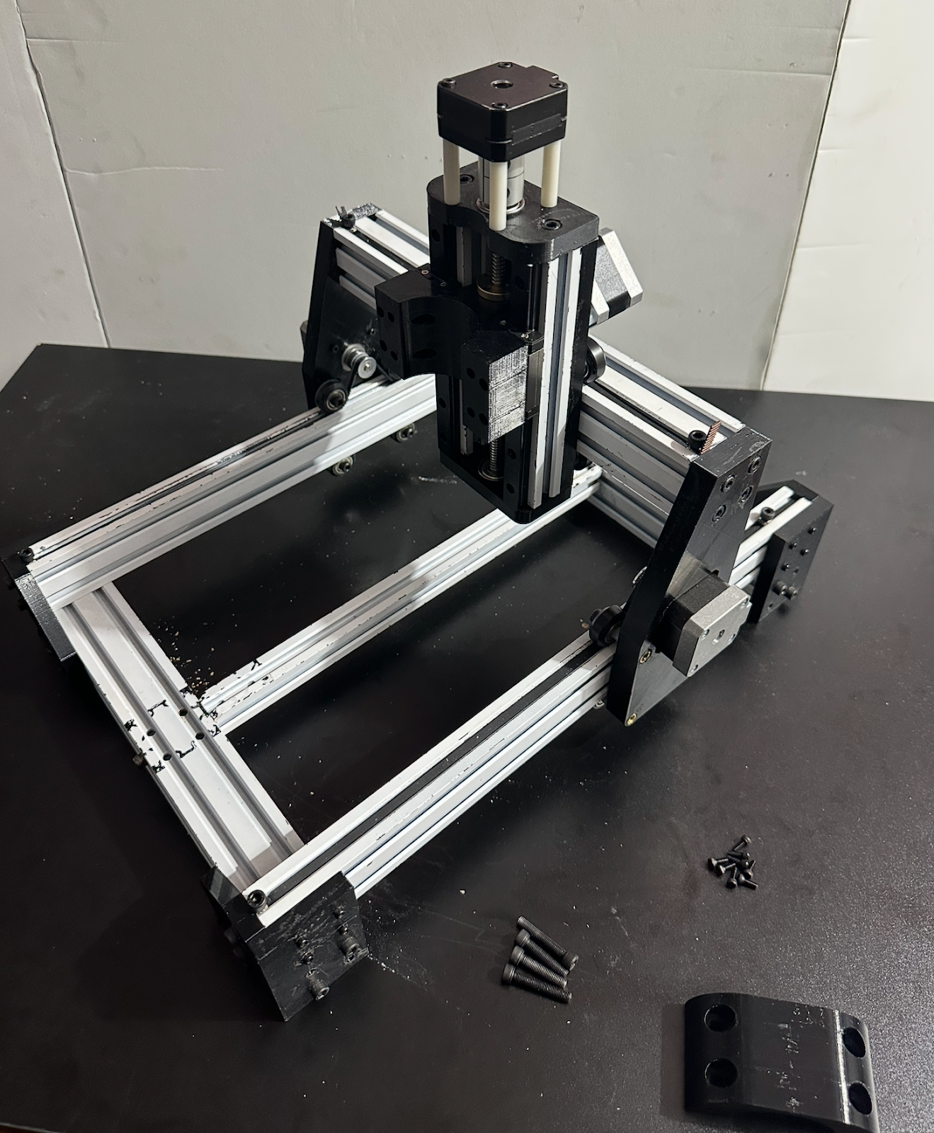
Finally, attach the spindle holder to the front of the carriage and tighten all hardware evenly.
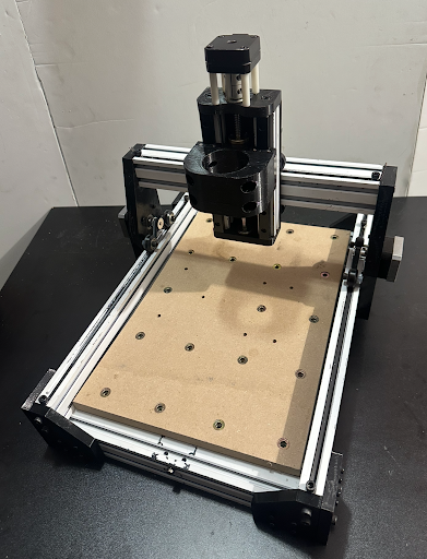
Completion
Your Ender-CNC mechanical build is now complete.
Verify that all axes move freely, screws are secure, and no rails bind during full-range motion.
Congratulations — the mechanical assembly is finished!
Proceed to the electronics and firmware configuration steps to bring your machine to life.