Preparation
The first stage of the Ender‑CNC conversion involves identifying reusable components from your Ender 3, preparing your workspace, and carefully disassembling the printer.
This ensures that all critical hardware is preserved and organized before beginning the frame assembly.
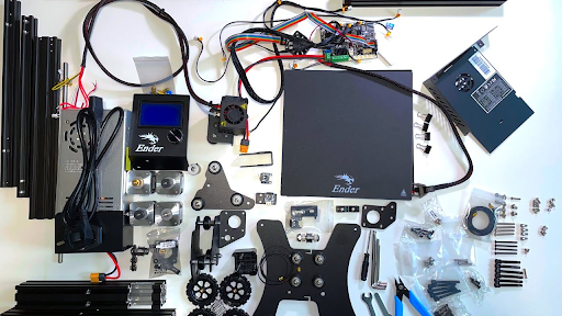
Identify Existing Components
Review your Ender 3 to determine which resources can be reused. Focus on:
- Lead screw and Z‑axis stepper motor
- X/Y stepper motors
- 2040 / 4040 aluminum extrusions
- V‑wheels, bearings, and spacers
- Corner brackets, T‑nuts, and fasteners
- Power supply and electronics (optional reuse)
Different Ender 3 models vary slightly in extrusion lengths and bracket geometry. You may need additional parts depending on your printer version.
If your printer has a single‑lead‑screw Z‑axis or custom frame variant, compare it to the provided CAD reference before reuse.
Workspace Setup
Before teardown, prepare a clean, well‑lit workspace.
Organize trays or boxes for small hardware such as nuts, bolts, and wheels.
Label each component as you remove it — extrusions and brackets can appear identical once separated.
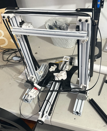
Disassembling the Ender 3
Carefully dismantle your printer in the following order:
- Remove the print‑bed assembly — detach the Y‑axis belt, carriage, and base extrusions.
- Unbolt the Z‑axis — remove the vertical column, lead screw, and motor.
- Disconnect all wiring — unplug steppers, end‑stops, and power leads.
- Remove electronics & PSU — store safely if planning reuse.
- Collect all fasteners — keep M3/M5 hardware and T‑nuts grouped.
Take reference photos throughout the teardown — they’ll make re‑assembly and alignment checks much easier.
Acquire Additional Components
After disassembling your Ender 3, review the parts that must be purchased or fabricated to complete the CNC conversion.
The Ender-CNC design reuses much of the printer’s original hardware, but several structural and motion components are new and must be sourced separately.
Typical required additions include:
- Extra 2040 / 4040 aluminum extrusions for the extended base and gantry
- 52 mm spindle motor with a compatible mount
- Brackets, couplers, and hardware for lead-screw and rail integration
- Protective enclosure or case for the CNC electronics and wiring
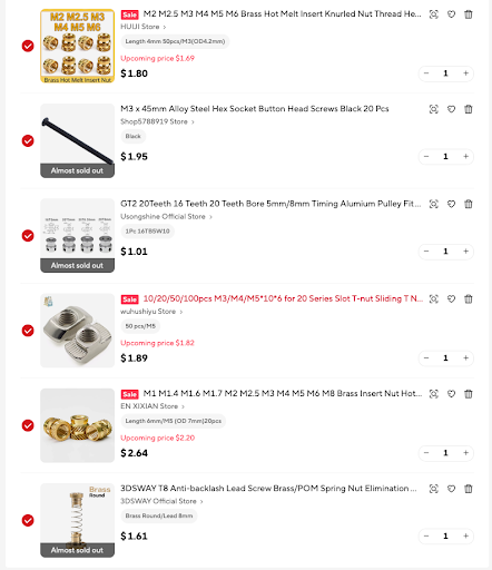
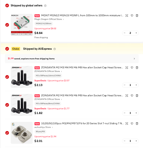
Refer to the /Assembly section in Github for full list of hardware specified in the design files.
Summary
By the end of this combined step, you should have:
- A fully disassembled Ender 3
- All reusable parts labeled and stored
- A list of missing components to order
- A clean workspace ready for base‑frame assembly