Z-Gantry Assembly
The Z-gantry introduces vertical motion to the Ender-CNC.
This stage requires careful alignment of extrusions, wheels, and motor mounts to maintain perpendicularity and eliminate binding.
Preparing the Vertical Extrusions
Cut two extrusions to 150 mm each — these form the Z-axis uprights.
They are derived from the Ender-3’s former top crossbar.
Insert M5 bolts through the gantry plate holes and secure T-nuts on the front end to clamp the extrusions in place.
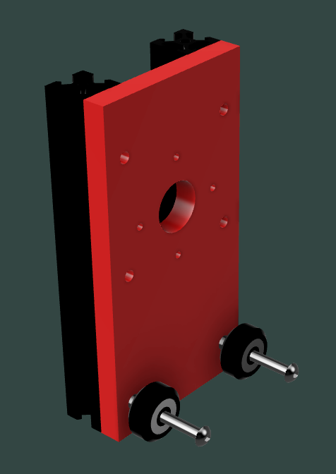
This process is slightly intricate — each bolt passes through a V-wheel, a panel, and the T-nut that locks to the extrusion.
Keep all fasteners loose until the assembly is fully aligned.
Mounting and Tensioning the Wheels
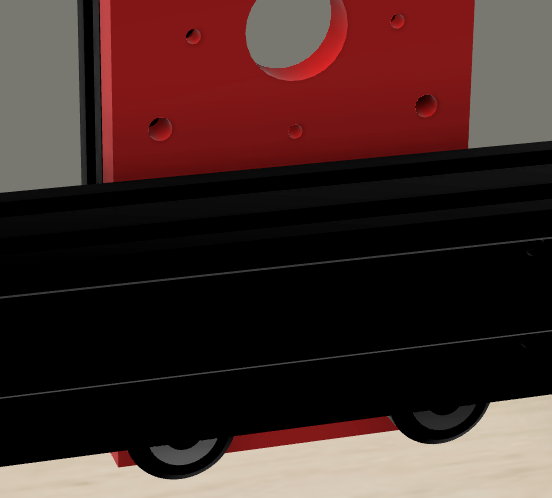
Align the gantry with the 4040 X-axis crossbar, then slide on the V-wheels and spacers.
Tighten gradually while verifying that motion is smooth across the rail.
Once alignment feels consistent, firmly tighten the upper fasteners to rigidly secure the vertical structure.
Smooth travel is more critical than preload — over-tightened wheels cause stiction and wear.
The gantry should glide under gentle hand force.
Motor Mount and Pulley Alignment
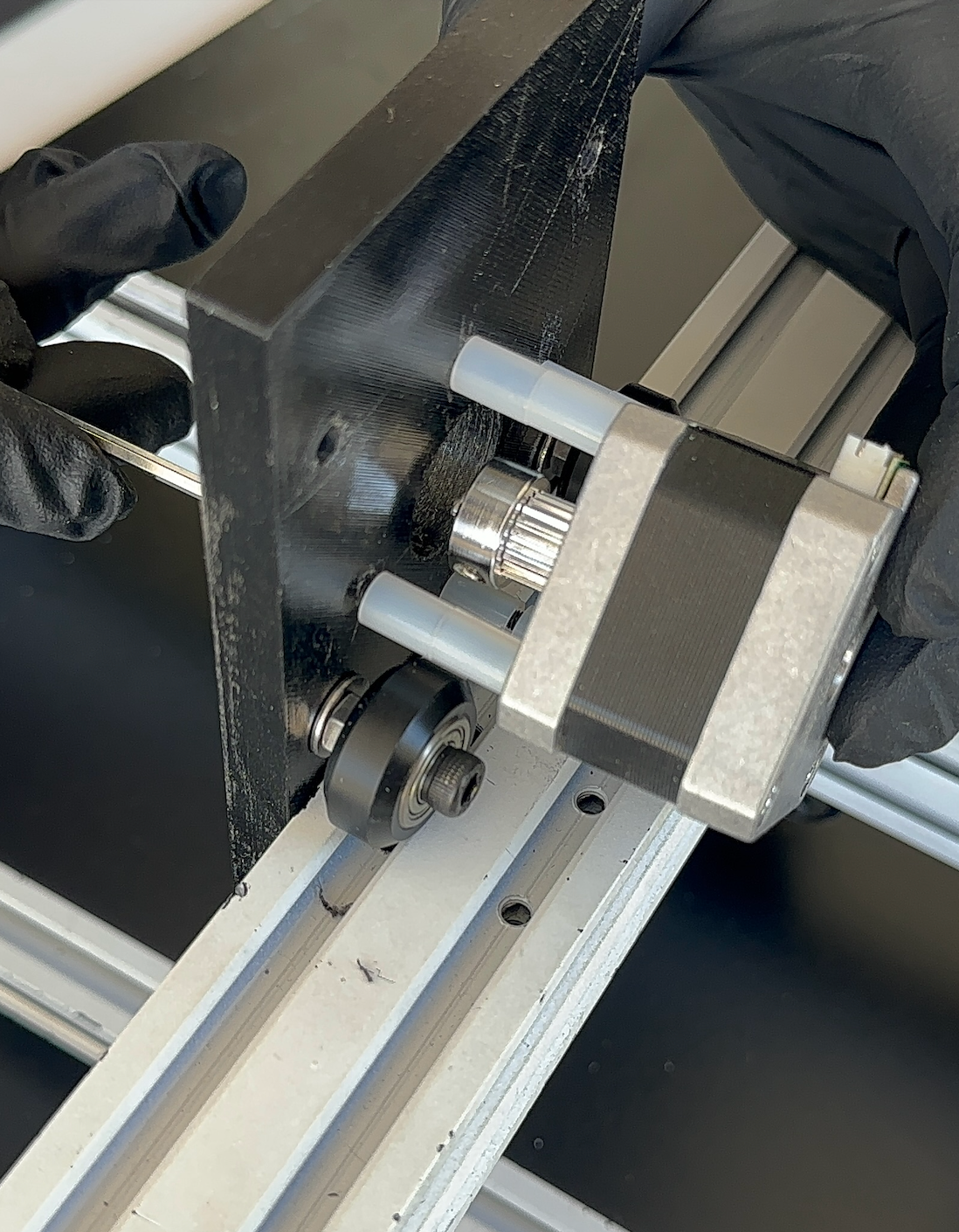
Attach the Z-axis stepper motor using spacers to ensure pulley alignment with the 4040 rail.
The pulley must be parallel to the extrusion to prevent lead-screw binding.
Note:
The image above omits the previous assembly step for clarity, but ensure both the upper and lower V-wheel sets are already installed before motor mounting.
Assembly Validation
- Check that both uprights are perpendicular to the base.
- Move the gantry by hand — it should travel evenly along both rails.
- Verify the pulley and lead-screw axis are vertically centered with no offset.
Summary
After completing this step, you should have:
- Two 150 mm vertical extrusions installed
- V-wheels and spacers tensioned correctly
- Z-axis motor mounted and pulley aligned
- Smooth, vertical travel with no play or binding