X-Axis & Drive Integration
The X-axis assembly establishes the top structural connection between the mirrored Y-gantry plates and enables synchronized motion.
This step also includes motor installation and belt routing, so alignment and belt tension are crucial.
Crossbar Installation
Start with the 4040 crossbar cut from the center section of the Ender-3’s original top rail.
The reference model measures 292 mm, but confirm the exact dimension based on your build tolerance.
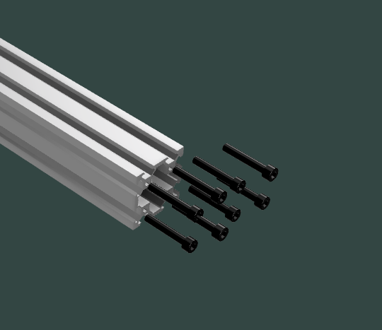
Hold the Z-axis column in position and secure it using eight M5 bolts threaded into the 4040 extrusion.
Use a tap if necessary — ensure both ends are parallel before tightening.

Support the gantry while tightening to prevent sagging or misalignment during assembly.
Y-Axis Motor Installation
Mount the Y-axis stepper motors on the inside faces of each gantry plate.
Use M3 bolts to secure standard NEMA 17 motors, aligning pulleys with the belt path.
Repeat on the mirrored side to complete both drives.
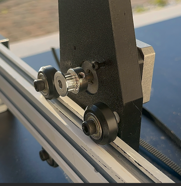
Belt Routing
This stage can be challenging if you’re new to GT2 belt setups.
The correct path is under the wheel, over the pulley, and back under the wheel, forming a continuous loop.
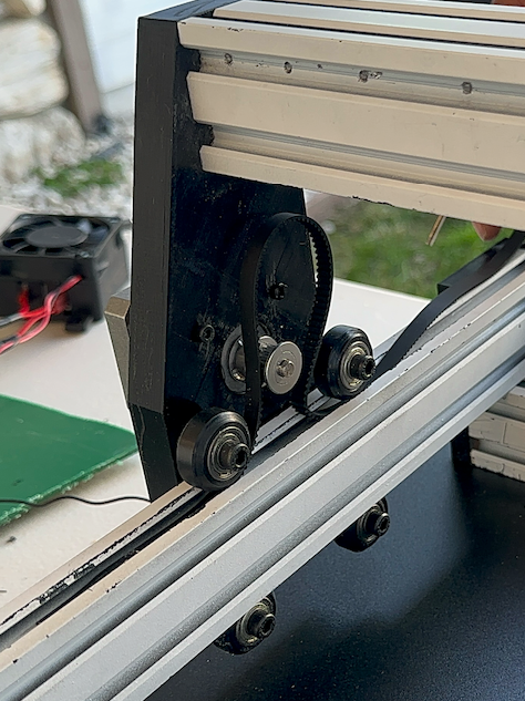
Tension the belt by tightening the T-nuts located at both ends of the extrusion.
Ensure even tension across both sides to prevent skewed travel.

Slightly over-tensioning the belts helps prevent backlash, but avoid excessive strain that could deform the wheels or motor shafts.
Alignment Check
Move the gantry manually along the full Y travel.
It should roll smoothly and evenly, with no binding or uneven resistance.
If friction occurs:
- Verify both belts are equal in length and tension.
- Confirm pulleys are aligned with the belt plane.
- Check that both gantry plates are parallel.
Summary
At the end of this phase, you should have:
- A secured 4040 X-axis crossbar
- Two Y-axis stepper motors installed and aligned
- Properly tensioned belts with free linear travel