Base Frame Assembly
The base frame is the structural foundation of the Ender‑CNC. It reuses sections from the Ender‑3 while adding new extrusions and brackets for rigidity. Follow each step carefully—alignment here sets the accuracy of the whole machine.
Preparing the Base Components
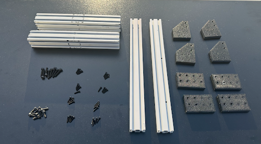
Begin with the components shown below. At this stage no extrusions need to be cut—remove the Z‑axis extrusion and the two side base pieces from the Ender‑3.
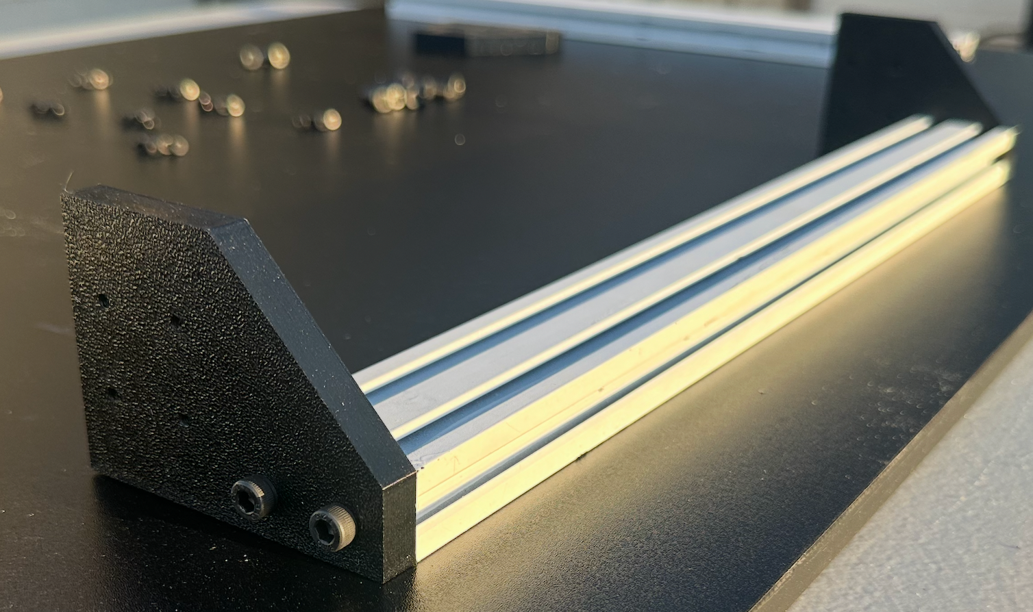
Insert bolts into the plastic angled brackets as illustrated.
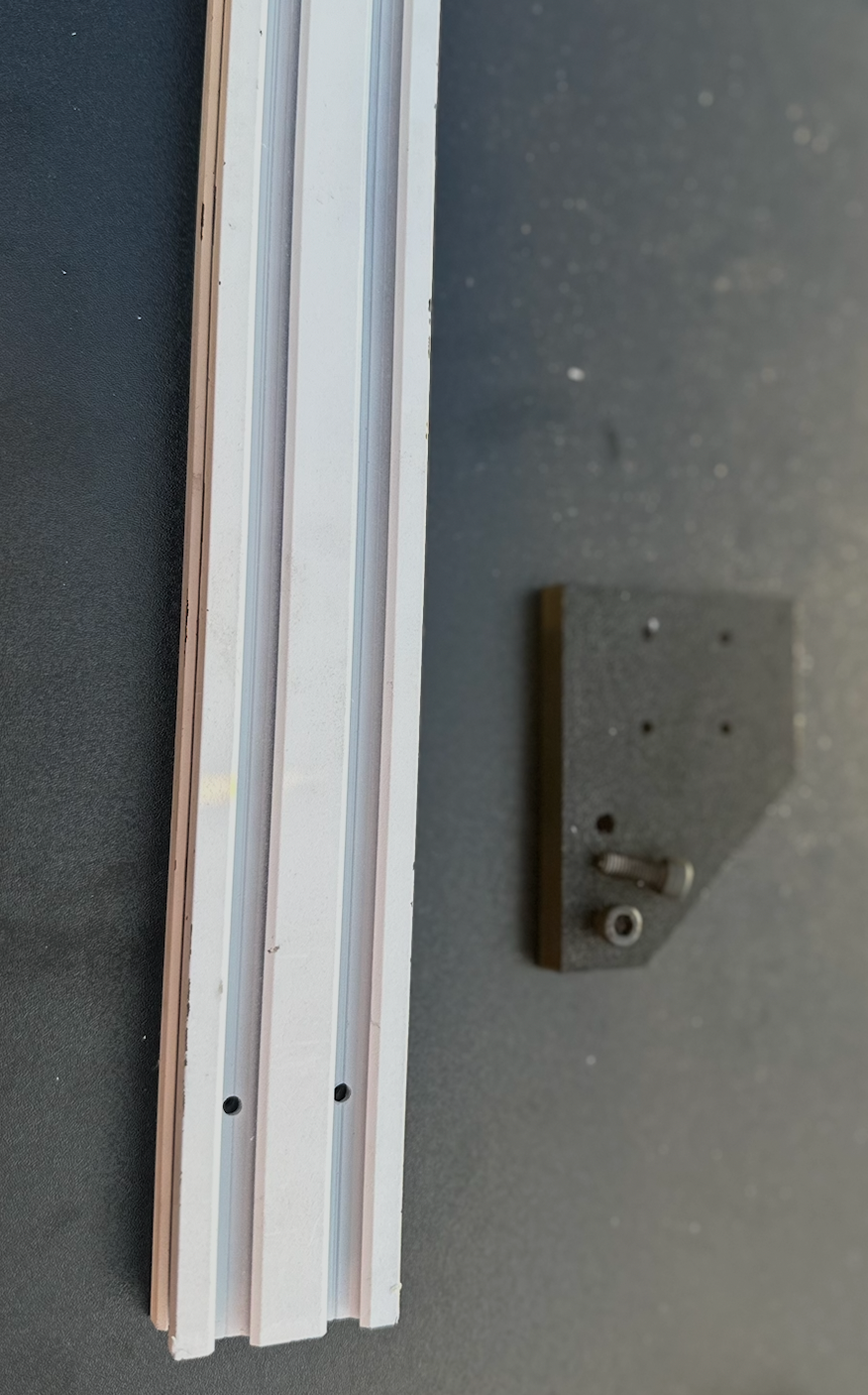
Attach the assembly to the 2040 extrusion. Depending on your Ender‑3 model, you may need to use a threading tap. Create a mirrored version for the opposite side.
4040 Cross‑Member Installation
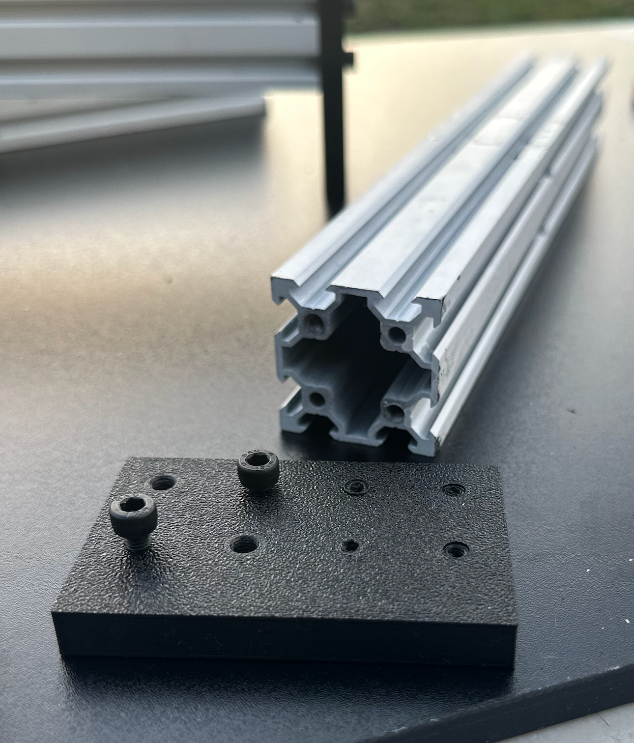
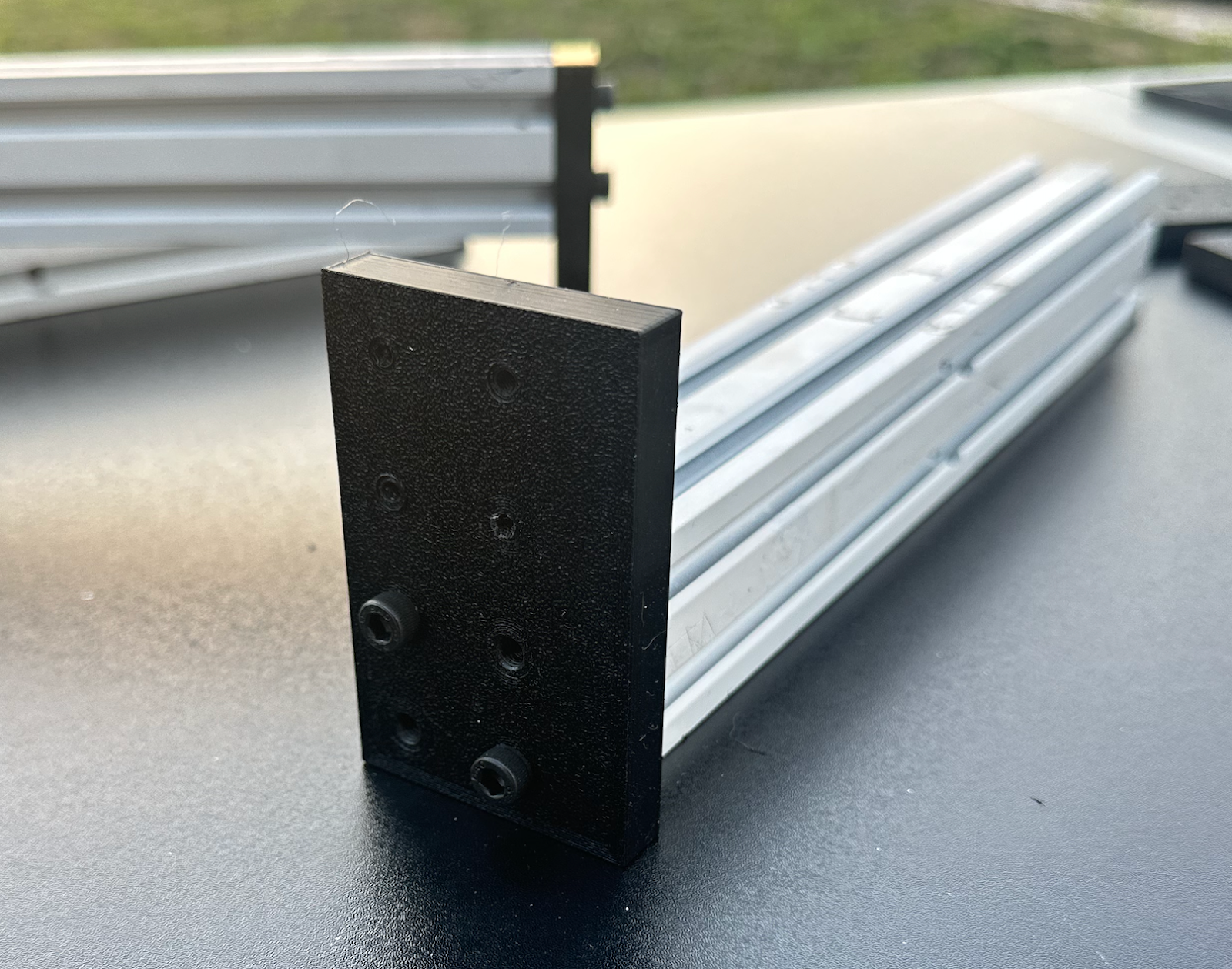
Insert M5 bolts into the rectangular bracket that interfaces with the 4040 extrusions.
Position the bracket on the extrusion and screw it in. Tapping may be necessary; not all four bolts must be installed at this time.
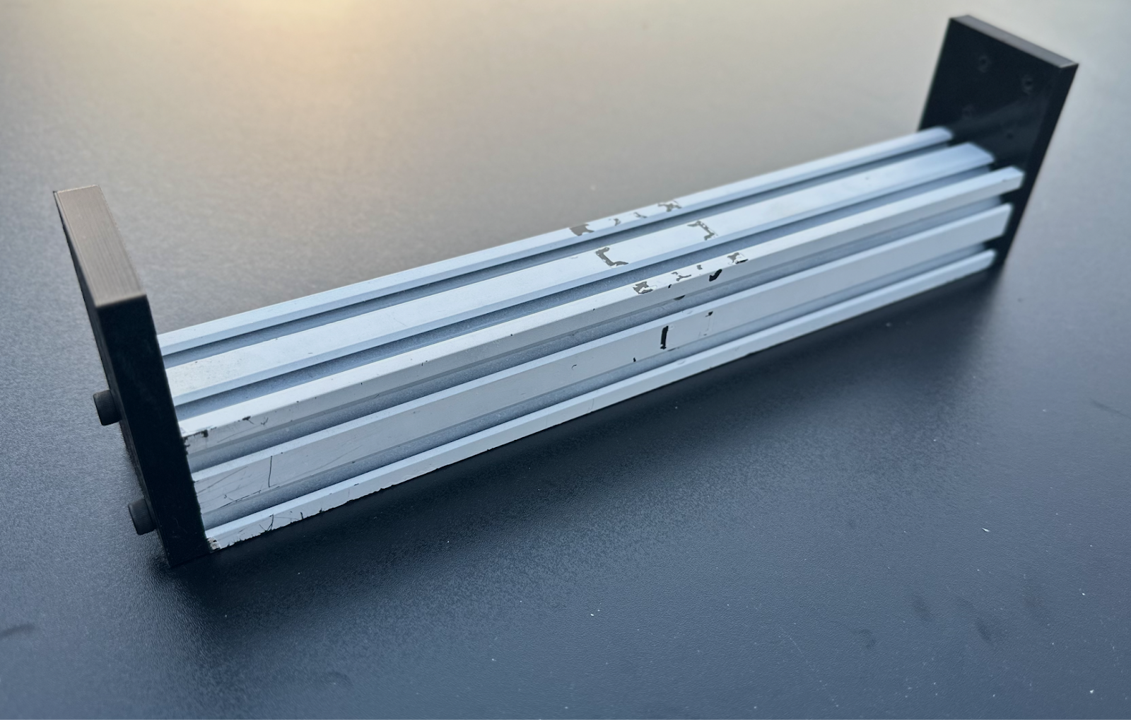
Repeat the process on the opposite side to create two of the assemblies shown.
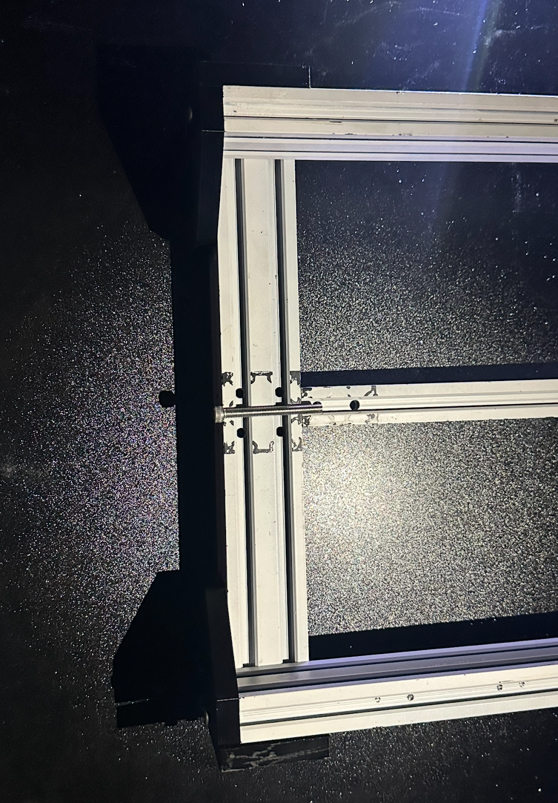
Corner Reinforcement & T‑Nuts
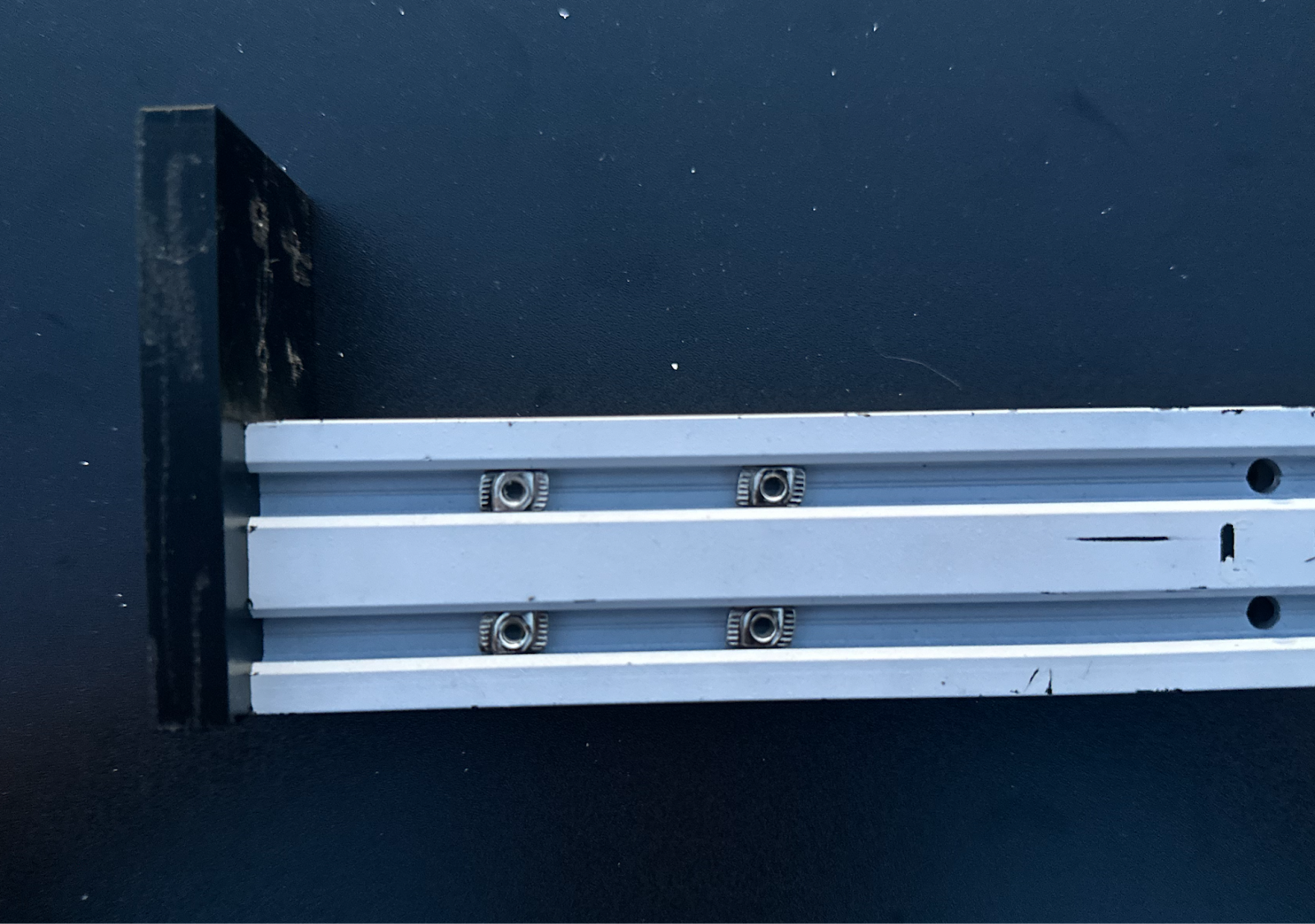
Insert M3 T‑nuts at each of the four corners—8 placements per corner → 32 T‑nuts and M3 bolts total.
If alignment seems unclear, refer to the following visual reference while placing the T‑nuts.
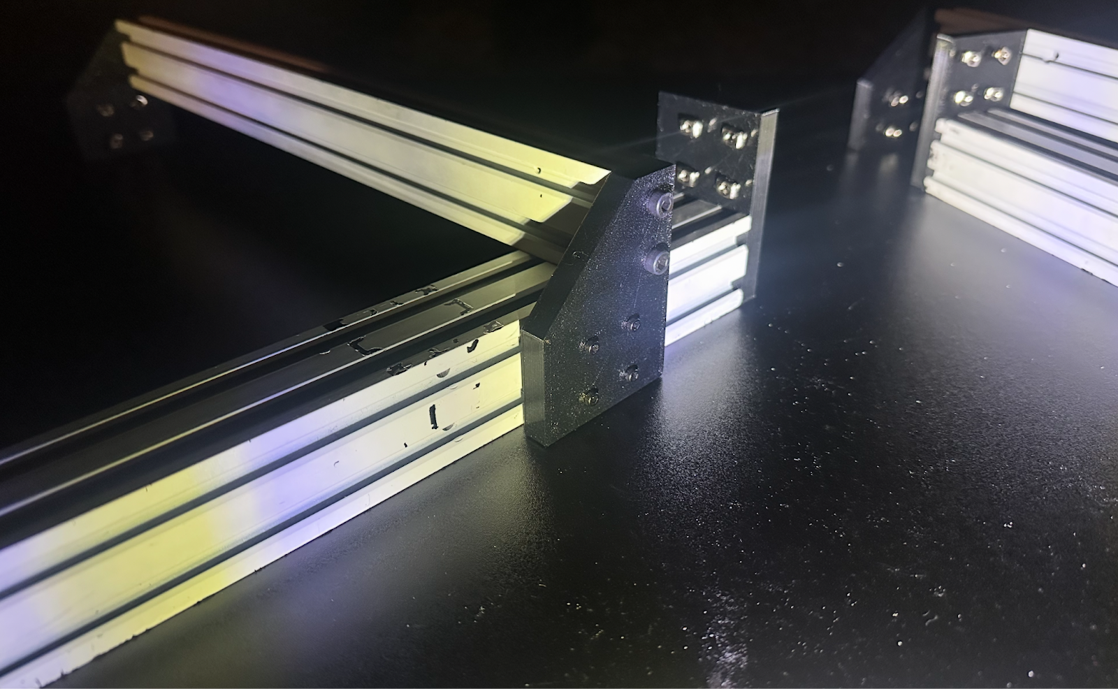
Ensure all four corners are firmly tightened. Using a machinist’s square is strongly recommended for alignment.
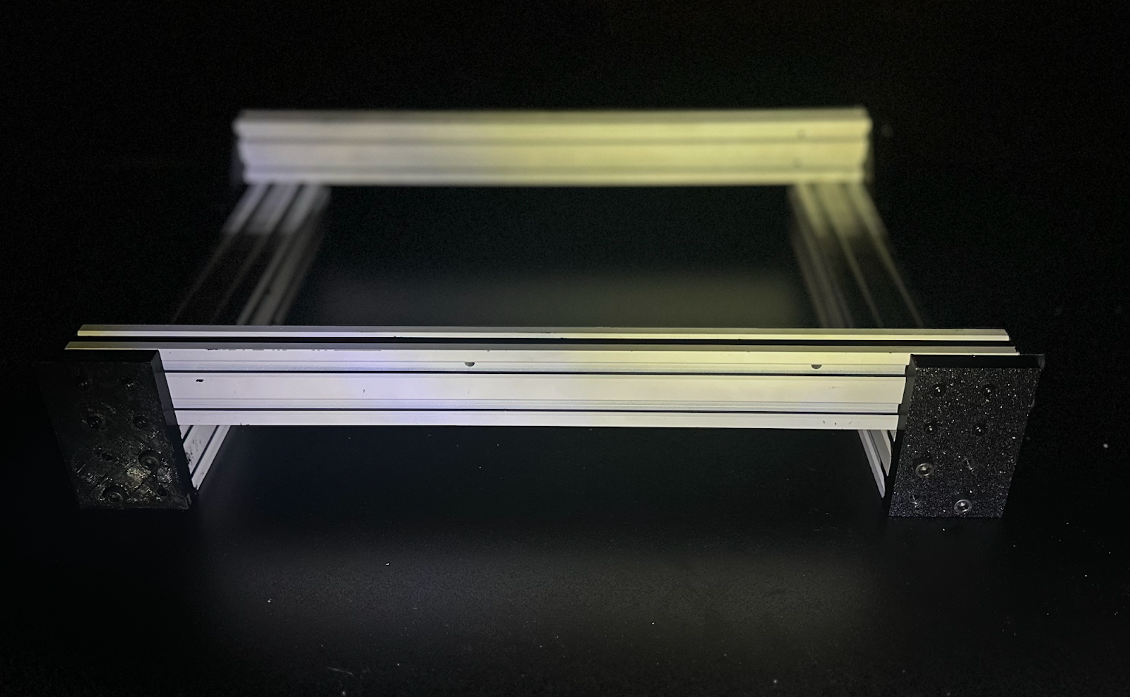
Frame Checkpoint
At this stage, the frame should resemble the example below.
Optional: Trim the X‑Rail
Optionally trim the Ender‑3 X‑rail (the piece that connects to the Z‑axis) to the desired length. Cutting to ≈ 320 mm improves rigidity.

Summary
You should now have:
- A rigid, square base frame
- Two mirrored 4040 assemblies installed
- All T‑nuts pre‑positioned for the upper gantry