Hardware
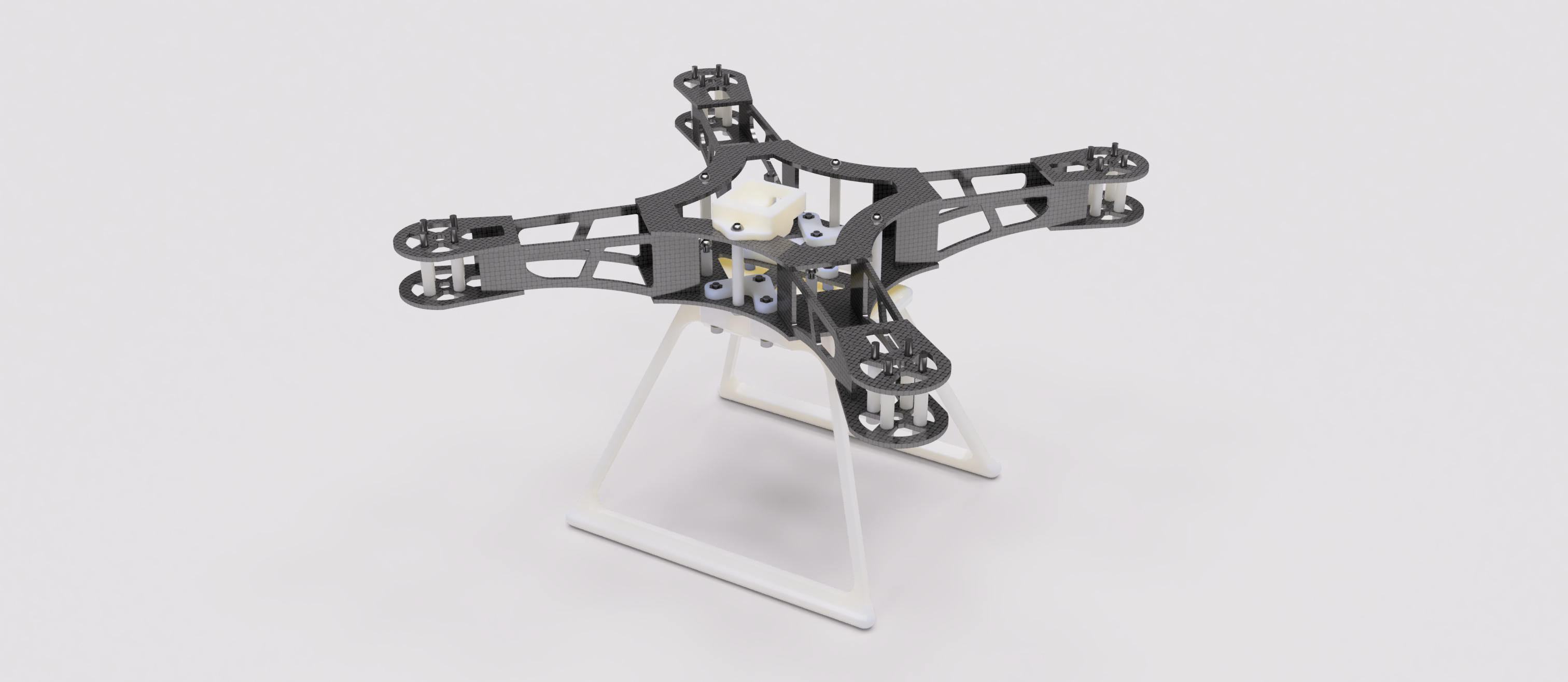
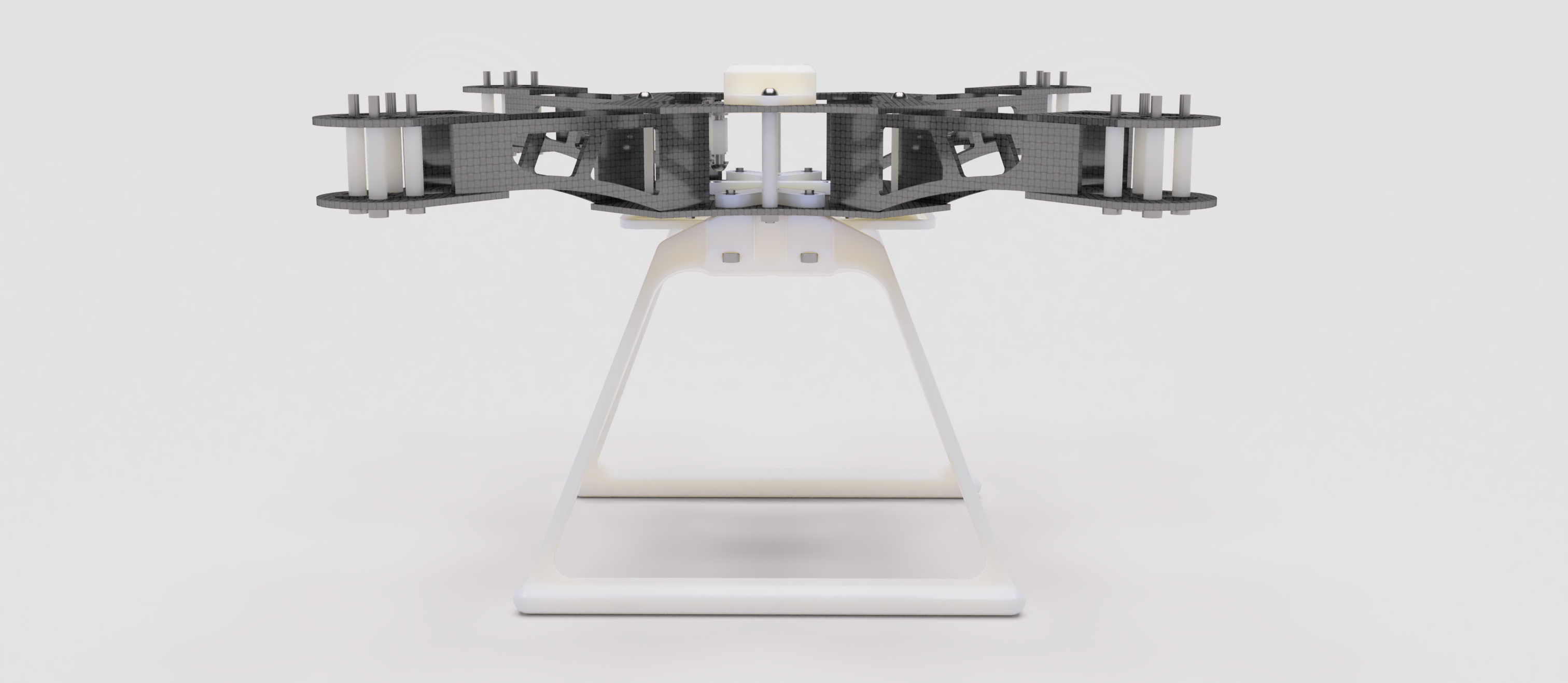
The hardware section covers the mechanical design, manufacturing, and assembly of the STM32-Quadcopter frame.
Both CNC-cut carbon-fiber and 3D-printed variants are supported, using the same mounting geometry.
Frame Design and Resources
All 3D and 2D models are publicly available from:
-
MakerWorld – Quadcopter 3D-Printable STM32 MCU Model
Recommended for downloading pre-sliced 3D print profiles and previewing assemblies. -
GitHub Repository –
/3.ModelsDirectory
Contains source CAD files (STEP, STL, DXF) and mechanical drawings for fabrication.
Each repository provides:
- 2D/3D Components (STL / STEP) — printable or editable for additive manufacturing.
- Assembly References (STEP, PDF) — showing part orientation and mechanical stack order.
Use the CAD assembly as the authoritative reference for hole spacing, standoff height, and overall mechanical alignment.
Carbon-Fiber Components
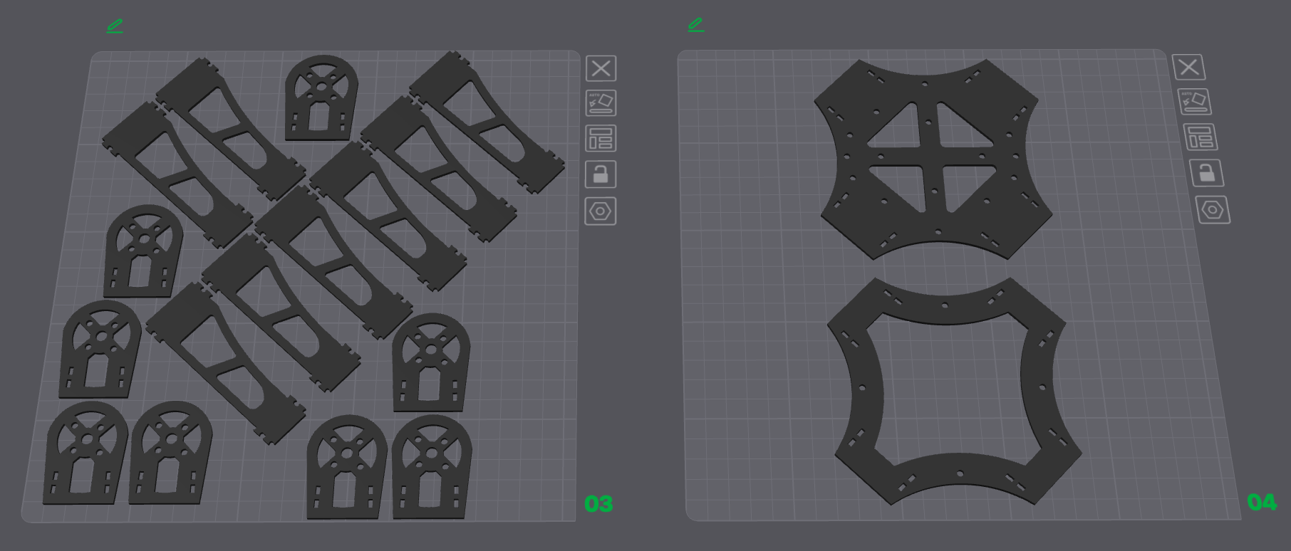
All carbon-fiber cut patterns are located under /3.Models/CF/.
When preparing for CNC cutting, ensure proper dogbones and edge tolerances are added for manufacturability and ease of assembly.
ABS / 3D-Printed Components
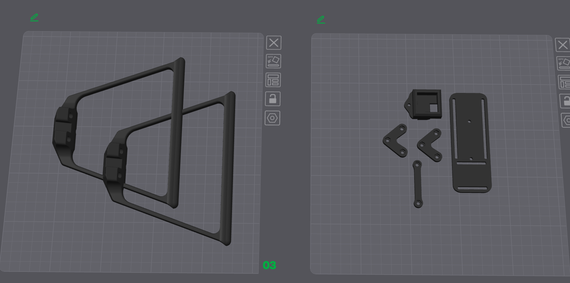
Use carbon-fiber reinforced filaments (PET-CF, PAHT-CF, PA6-CF, or PPS-CF) for structural parts such as arms and center plates.
Non-critical covers or spacers can be printed in ABS or ASA.
Mechanical Components BOM
| Item Name | Qty |
|---|---|
| M3 Hex Nut | 19 |
| M3 × 12 mm Button Head Bolt | 2 |
| M3 × 20 mm Button Head Bolt | 7 |
| M3 × 20 mm Socket Head Bolt | 6 |
| M3 × 30 mm Socket Head Bolt | 16 |
| M3 × 35 mm Button Head Bolt | 3 |
| M3 × 40 mm Button Head Bolt | 1 |
| Nylon Spacer 3-5-11.2 | 8 |
| Nylon Spacer 3-5-20 | 16 |
| Nylon Spacer 3-5-30 | 4 |
| Nylon Spacer 3-5-5 | 2 |
Assembly Reference
For complete mechanical orientation, download the full assembly STEP file from MakerWorld .
This includes exploded views and correct spacer stacking for each section of the frame.