Electronics
The PCB is designed in KiCad 8. All project files and fabrication data are stored in the repository’s Electronics/ folder. You can access them directly via the GitHub repository or download the Gerber package for production.
Project Structure
1. Electronics/
  ├── Extra/                  ← STEP and auxiliary CAD models
  │   ├── *.step
  │   └── …
  ├── Hardware-backups/       ← backup versions of KiCAD files
  │   └── …
  ├── Production/             ← Gerber output for fabrication
  │   ├── Hardware-B_Cu.gbl
  │   └── …
  ├── Hardware.kicad_pcb      ← KiCAD PCB layout
  ├── Hardware.kicad_sch      ← KiCAD schematics
  ├── Hardware.kicad_pro      ← KiCAD project
  ├── JLCPCB.kicad_dru        ← JLCPCB DRC rule file
  ├── Production.zip          ← compressed Gerber ready for upload
└── Schematics.pdf ← exported schematic referenceProduction.zip to JLCPCB or any preferred manufacturer. Ensure the 2-layer option and 1.6 mm FR‑4 thickness are selected.Electronics Bill of Materials
This list covers the main electronic components required for assembling the quadcopter’s power and control system. For detailed SMD references, see the Schematics.pdf file in the repository.
| Component | Qty |
|---|---|
| RS2205 BLDC Motor | 4 |
| BLHeli_S 20 A ESC | 4 |
| 5030R Propeller | 2 |
| STM32F411CEU6 “Blackpill” | 1 |
| MPU6500 / MPU9250 Module | 1 |
| BMP280 Module | 1 |
| 330 µF @ 50 V Capacitor | 1 |
| FS-iA6B Receiver | 1 |
| FS-iA6B Transmitter | 1 |
| Ovonic 1500 mAh 120 C 3 S Battery | 1 |
| XT60 Connector | 1 |
SMD Components
Gerber files and the pick-and-place BOM are located in the same folder. You can import them directly into JLCPCB’s assembly tool.
Refer to Schematics.pdf in the repository for precise SMD part numbers and values. All passive and IC components used in the design are annotated there.
Pin Assignments and Wiring
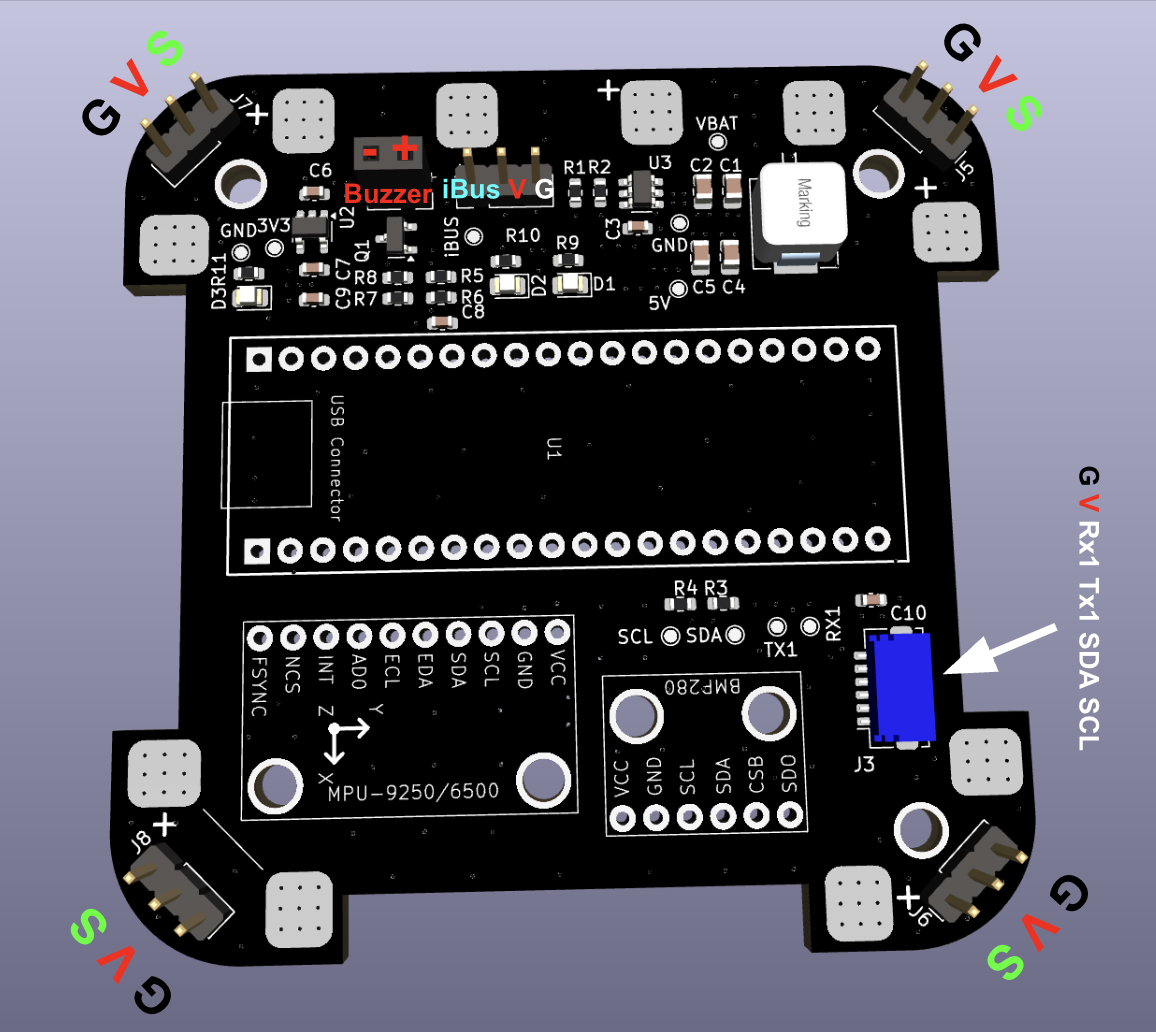
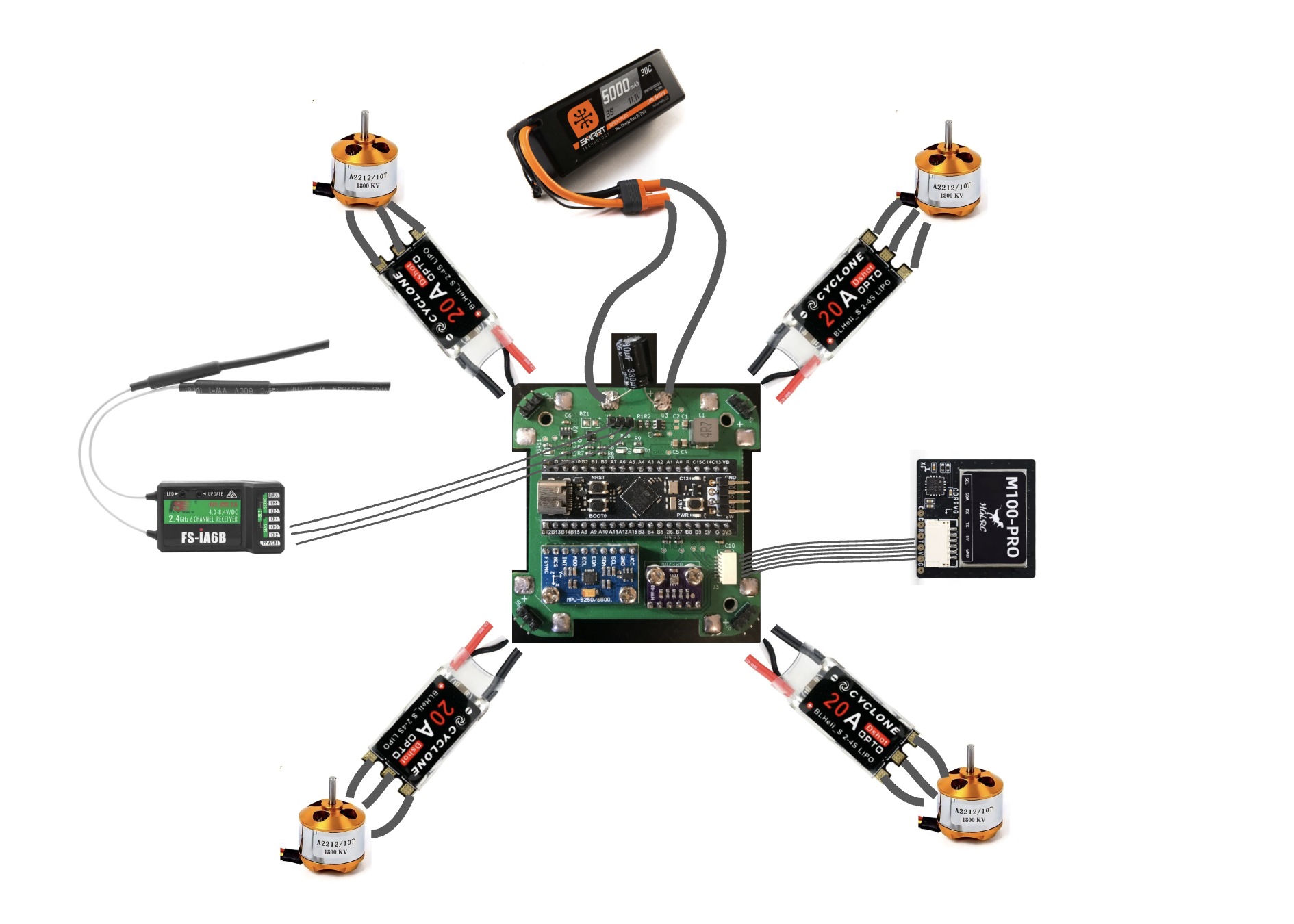
Diagrams above are conceptual and not actual wiring — follow the strict pin assignments in the KiCAD schematic.
GPS (UART1) Wiring
Ensure connectors are wired correctly according to the pinout:
RX1 → GPS TX, TX1 → GPS RX
Spike Filtering and Power Stability
One or more bulk electrolytic capacitors are recommended to protect against voltage spikes. Use an electrolytic capacitor such as 330 µF @ 50 V and place it between VBAT and GND near the input. For extra protection, add a TVS diode clamping at approximately 12 V.