Firmware
Build
The firmware used is INAV v6.0.0 (github link ). This project does not support INAV v7+ currently due to USB issue. If one wants to modify the target file or other configurations of the firmware, they must rebuild the binary. Follow this guide to build:
Prerequisites
- CMake ≥ 3.15
- Ninja
- gcc-arm-none-eabi toolchain
Clone INAV
git clone https://github.com/iNavFlight/inav.git
cd inav
git checkout 6.0
Add Target
Copy the entire 2.Firmware/GYW_BLACKPILL_F411 folder into the local INAV repository under src/main/target/ so that it ends up as:
inav/
└── src/
    └── main/
        └── target/
            ├──  GYW_BLACKPILL_F411/
            └── ...
Patch Code
INAV 6.0 doesn’t support a 25 MHz HSE clock by default, so if your board (like the Blackpill F411) uses a 25 MHz crystal, you must update the PLL setup in src/main/target/system_stm32f4xx.c as follows:
In system_stm32f4xx.c, locate the PLL setup region and modify it as follows:
#if defined(STM32F40_41xxx) || defined(STM32F427_437xx) || defined(STM32F429_439xx) || defined(STM32F401xx) || defined(STM32F469_479xx) || defined(STM32F446xx) || defined(STM32F410xx) || defined(STM32F411xE)
+   #if HSE_VALUE == 25000000
+       #define PLL_M   25
+   #elif HSE_VALUE == 24000000
-   #if HSE_VALUE == 24000000
        #define PLL_M   24
    #elif HSE_VALUE == 16000000
        #define PLL_M   16
    #elif HSE_VALUE == 8000000
        #define PLL_M   8
    #else
        #error Invalid HSE_VALUE
    #endif
#else
    #error Undefined CPU
#endif
Build
Ensure that you have installed all dependencies. Inside the inav root repository execute:
mkdir -p build && cd build
cmake .. -G Ninja \
  -DBOARD=GYW_BLACKPILL_F411 \
  -DCMAKE_TOOLCHAIN_FILE=../tools/cmake/toolchain-arm-none-eabi.cmake
ninjabuild/inav_6.0.0_GYW_BLACKPILL_F411.hexFlash
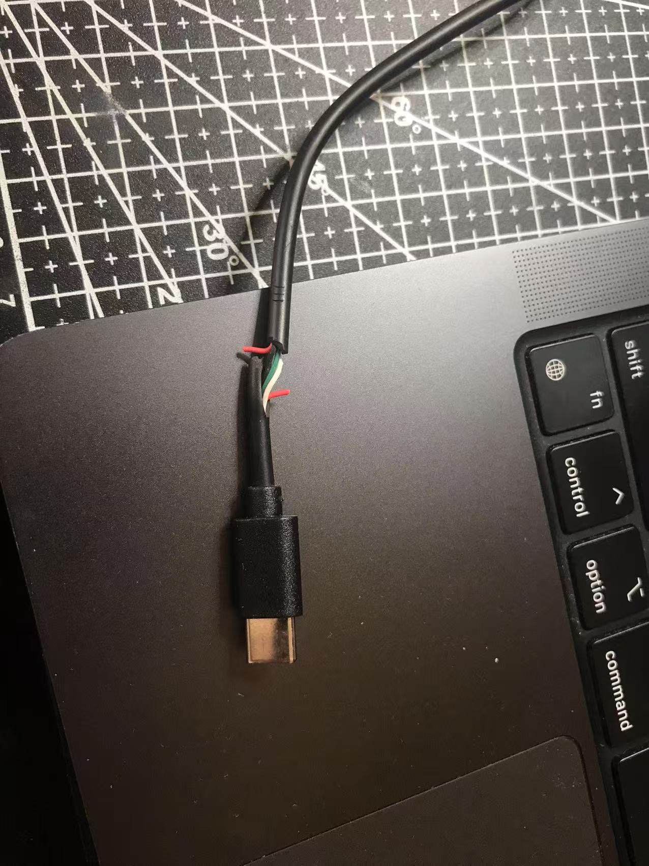
First, download the INAV Configurator v6.0.0 from this link . Once installed, launch INAV Configurator and connect to the Blackpill via USB. Cut the red wire in the USB cable to prevent it from powering the Blackpill. Instead, power the flight controller using an external 3S battery.
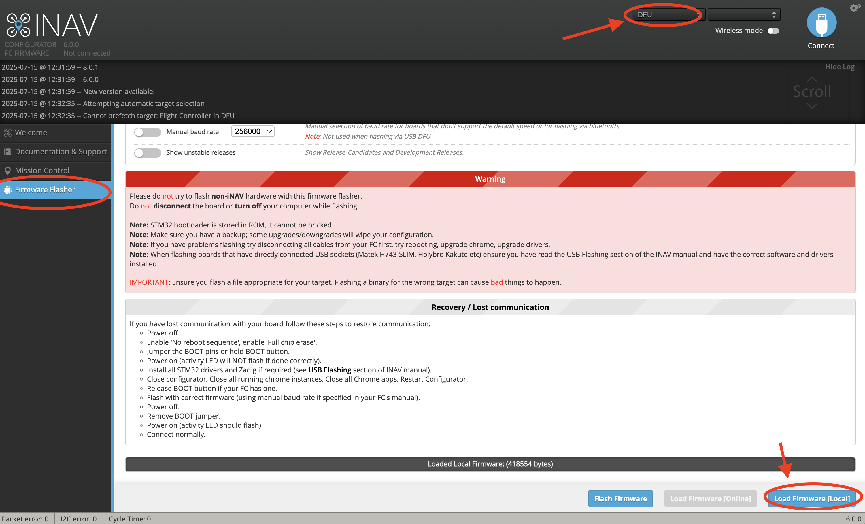
To enter DFU mode, hold the BOOT button on the Blackpill while powering it on. Alternatively, you can press RESET while holding the BOOT button. When in DFU mode, the blue LED on the Blackpill will be off, and the board should appear in the INAV Configurator’s drop-down menu as a DFU device. Move to the Firmware Flasher tab on the left. Click Load Firmware, select the file inav_6.0.0_GYW_BLACKPILL_F411.hex (found in the firmware folder), then click Flash Firmware.
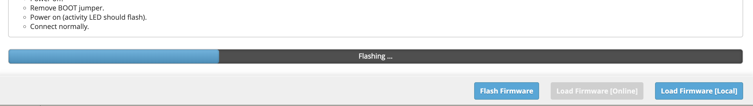
A progress bar will appear during firmware flash.
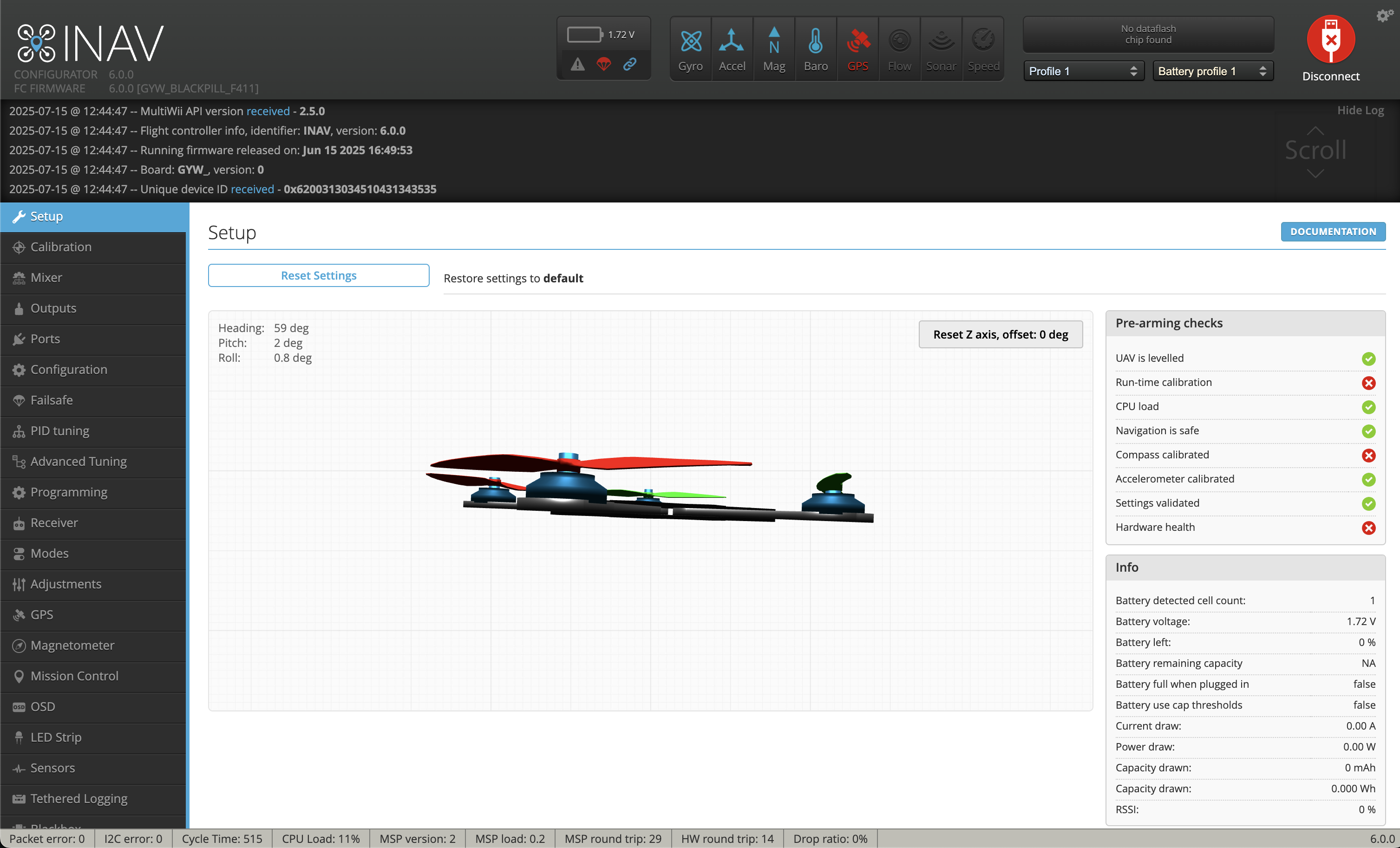
When the firmware is successfully flashed, click connect. The configuration menu should show up.
MPU9250 Issue
If you are using a MPU9250 module, you may encounter the problem that INAV does not recognize the accelerometer. This is due to many boards labeled MPU9250 actually house only an MPU6500 (omitting or substituting the magnetometer). Since drones often use an external magnetometer, this usually isn’t critical if your accelerometer and gyro (MPU6500) work.
To identify your chip, read the WHO_AM_I register (0x75) via I²C (use an Arduino or something similar to do this part). Example Arduino code:
#include <Wire.h>
const uint8_t MPU_ADDR     = 0x68; // I²C address
const uint8_t WHO_AM_I_REG = 0x75;
void setup() {
  Serial.begin(115200);
  Wire.begin();
  delay(100);
  Wire.beginTransmission(MPU_ADDR);
  Wire.write(WHO_AM_I_REG);
  if (Wire.endTransmission(false) != 0) {
    Serial.println(F("no device found")); while (1);
  }
  Wire.requestFrom(MPU_ADDR, (uint8_t)1);
  if (Wire.available()) {
    uint8_t id = Wire.read();
    Serial.print(F("WHO_AM_I = 0x"));
    Serial.println(id, HEX);
  } else {
    Serial.println(F("no data returned"));
  }
}
If it prints 0x71, it’s MPU6500; 0x73 indicates MPU9250.
The current binary file and target is configured for MPU6500. To use MPU9250, comment out the block for MPU6500 and uncomment the MPU9250 block in the target file. Rebuild the binary and flash. It looks like this:
#define USE_IMU_MPU9250
#define IMU_MPU9250_ALIGN   CW0_DEG
#define MPU9250_CS_PIN      PB12
#define MPU9250_SPI_BUS     BUS_SPI2
Configuration and Setting Up
Follow the standard INAV configuration procedures for sensor calibration, receiver setup, and motor output mapping.
Useful references for setup and tuning:
-
Complete INAV Setup Tutorial (YouTube – Painless360)
Excellent walkthrough video showing full configuration steps including receiver binding, sensor calibration, and flight mode setup.
Once firmware flashing is complete, connect via INAV Configurator and proceed through the calibration wizards. Ensure:
- The board orientation matches your frame mounting.
- All sensors (gyro, accelerometer, barometer, and GPS) initialize correctly.
- Receiver channels are mapped correctly.
- Motor direction and mapping configured.
- Flight modes and failsafe conditions are configured before first flight.